|
Didja Know? |
|
|
|
T/C
Crankshaft Issues? |
|
Article On Crankshaft Shifting !!! |
|
HARLEY T/C CRANKSHAFT SHIFTING |
| |
|
What is it? |
| |
|
What causes it? |
| |
|
What is the solution? |
|
|
|
|
What
is it?
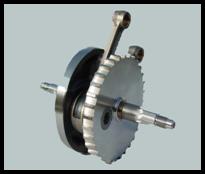
Harley crankshafts, both original
equipment and aftermarket, are constructed in three pieces:
the sprocket flywheel, the pinion flywheel and the crank pin
that joins them. The crank pin is secured to the flywheels
by a press, or interference fit. No other method of
fastening is used by the factory. Since the rods are inline
and do not have removable caps, the rods must be installed
when the crankshaft is pressed together. The figure at the
right illustrates the crankshaft configuration and
components. |
 |
|
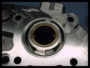
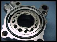
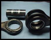
The problems occur when the press fit on
the crank pin slips, allowing the flywheels to go out of
balance and alignment. This shifting causes the crankshafts
to become eccentric, causing excessive oscillation (run out)
on the pinion and sprocket shafts. This results in the
damaging of the cam plate, oil pump, cam chain tensioner and
main bearings. On the 2007-Up engines, it also causes the
automatic primary chain tensioner to over-adjust. The
primary chain will then over-tighten. When this happens, it
overloads the left crankshaft main bearing and the mainshaft
bearing in the inner primary case leading to fatigue and
eventual failure. We have also found that on engines that
have the “Screamin Eagle” compensator installed, it will
cause the sprocket shaft to bend and twist. See Figures 1,
2, and 3 below. |
|
 |
|
 |
|
 |
|
Figure 1 |
|
Figure 2 |
|
Figure 3 |
|
| |
|
We at Hotshot Motorworks
have developed a solution to this
problem which will come later in the
article.
|
| |
|
Our customers often are
told that the Harley T/C camshaft is a piece of junk and
make of inferior materials with improper heat treatment. We
have found this is not the case and are convinced that the
manufacturing, materials and, heat treatment are first
rate. Hot Shot Motorworks has been working
with Harley Davidson press together crankshafts since their
inception in 1972 (XR750), and have become very
knowledgeable of the design and modifications required to
make it virtually a bullet proof crankshaft. Hot-Shot
Motorworks has reconditioned 1,000’s of Harley
Davidson T/C cranks since it was introduced in the T/C
engine in 1999. The crankshaft that is used in the XR750 is
virtually the same as what is being used in today’s T/C
engine other than a difference in the stroke and rod
length. Hot-Shot Motorworks has incorporated
similar modification’s that were performed on the XR750
crankshaft that would rev 8,500 – 9,000 continuous
rpm’s in a engine that produced 2.30 horsepower per cubic
inch, into today’s modified T/C engines which average about
1.25 – 1.30 horsepower per cubic inch and turn a maximum of
6,000 – 6,500 momentary rpm’s. |
| |
|
What Causes It?
Hot-Shot Motorworks took the initiative to
disassemble and dissect each part that consists of the T/C
crankshaft assembly and after many hours of research, we
found that the problem lies within the way the T/C
crankshaft is “Balanced”, “Torsional Vibration”,
and “Torque Spike”. |
| |
|
Initially we
thought the problem of crankshaft shifting had to do with
the fitment of the crankpin into the flywheel half. But
after designing and installing crankpins with larger
diameters (which increases the interference fit) we found
that the problem of flywheel shift still existed.
|
| |
|
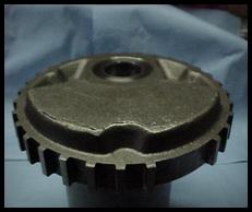
In addition, we found that the O.E.M. flywheel halves are
“Engineered Balanced” and this is where part of the
problem lies. “Engineered Balancing” is where the
engineers at Harley Davidson have figured out where the
heavy spot in the flywheel is located and have designed the
casting mold to create a void in the forging/casting to
remove material from each flywheel, which should bring the
flywheel close to balance tolerance +/- a small percentage.
See Figure 4. The problem with using this method is that
due to core shift in the forging/casting of the flywheel,
there will be variations in where the void is located in the
counterbalance. When this happens, it changes the location
and depth of the void that is cast into the flywheel causing
each flywheel half to be out of balance. The core shift can
also cause the void (Figure 4) to be either closer to the
mainshaft, which will remove more material from the
counterbalance or further away from the mainshaft which will
allow not enough material to be removed from the flywheel.
The core shift can also change the depth of the void
to the point where it is not located at the proper depth,
therefore will cause the void to be either cast to deep or
not deep enough. The core shift can also change the
rotational location of the void to where it is not located
at the proper degree of rotation from the centerline of the
crank pin. The variation of the core shift may be
different on each flywheel half and thus causes the
crankshaft assembly to be either over balanced or under
balanced. |
|
 |
|
Figure 4 |
|
| |
|
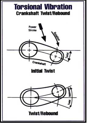
The most important cause we
found was due to the design of the Harley-Davidson
crankshaft. It has an enormous amount of “Torsional
Vibration” and Torque Spike”. “Torque
Spike” happens each time the air/fuel mixture inside the
combustion chamber is ignited. The combustion that results
creates a “Torque Spike” from an extremely rapid rise
in cylinder pressure. This pressure, applied to the top of
the piston, becomes the force that is applied to the
crankshaft through the connecting rod to make the crankshaft
rotate. Each “Torque Spike” is like a huge hammer
blow. In fact, it hits with such intensity that it actually
deflects and twists the crankshaft. This twisting action and
the resulting rebound (as the crankshaft snaps back in the
opposite direction) are known as “Torsional Vibration”.
If not adequately controlled, “Torque Spike”
will cause main bearing failure, main shaft bending, main
shaft twisting, crankshaft shifting and possible crankshaft
breakage. The Harley crankshaft
only has one connecting rod journal which is located 2.00”
out from the center line of the mainshaft (1999-2006 models
– 4.00” stroke) and 2.1875” out from the center line of the
mainshaft (2007-Up models – 4.375” stroke). It also has a
severe rod angle which creates leverage and also causes
additional twisting of the crankshaft halves where the crank
pin is installed in each half. Figure 5 shows how the
crankshaft reacts when the air/fuel mixture in the
combustion chamber is ignited. The longer the stroke the
more severe the “Torque Spike” becomes. Some
companies recommend lightening the flywheels so the engine
will rev quicker. But when material is removed from the
flywheel halves it actually weakens the flywheel halves
allowing more twist in the crankshaft assembly. This allows
more “Torsional Vibration” and ”Torque Spike” which
creates more problems. It has also been found that
crankshaft assemblies that have smaller crank pin diameters
will not produce enough frictional area where the crank pin
is pressed into the flywheel half to keep the flywheels from
shifting. |
|
|
| |
|
Why Does This Cause The
Flywheels To Shift?
As we mentioned earlier in the article, the Twin Cam
crankshaft is a three (3) piece assembly which consists of a
left flywheel half (sprocket side), common crank pin and
right flywheel half (pinion side). Although there is an
interference fit between the crank pin and the inside
diameter of the flywheels where the crank pin is inserted,
there still isn’t enough pressure to keep the flywheel
halves from slipping and rotating relative to the crank
pin. Once this happens, the two flywheels are no longer in
phase with each other. This causes excessive “Torsional
Vibration” which transfers through the crank pin from
one flywheel to another. Depending on the natural frequency
of the crankshaft and the engine speeds, the forces caused
by these vibrations become very significant. Now let’s add
in the “Torque Spike”. The “Torque Spike” adds
to the forces and amplifies the vibrations making the
situation much worse. The magnitude of these forces
occurring rapidly and changing with engine speed fatigues
other components in the system, causing eventual failure. |
| |
|
When the Harley Davidson factory
assembles the stock crankshaft, which is done with robotics,
it is supposed to be trued to less than .001” on each
flywheel half. This is an acceptable tolerance. That is why
you didn’t feel any vibration when your motorcycle was
new. But over the years of riding the “Torsional
Vibration” and “Torque Spike” keeps transferring
forces back and forth thru the crank pin, slowly causing
crankshaft twist and allowing the flywheels rotate and
shift. Typically most crankshafts we repair have an average
of about 15,000-20,000 miles on them before the shifted
flywheels start causing damage to the cam plate and oil pump
or the customer starts to complain about a vibration. When
the runout on the pinion shaft side is checked, it can be
anywhere from .010” up to .100”. The acceptable run out
tolerance is .004” - .006” for chain drives and less than
.004” for gear drives. When the runout gets excessive, cam
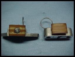
plate and oil pump issues will occur. Another indication
that crankshaft shifting is occurring is when the outside
cam chain tensioner shoe shows signs of wearing (See Figure
6). This is caused by the oscillation of the pinion shaft,
which allows the cam chain to run loose in one spot and
tight in another spot. If the problem is resolved early on,
it may reduce the cost of replacing the oil pump, cam plate
and will save the bearing surface of the pinion shaft. |
 |
|
Figure 6 |
|
| |
|
What Is The Solution? |
|
The only solution is to rebalance and weld the
crankshaft assembly. Each flywheel half must be
balanced separately prior to assembly and welding.
We have tried dynamic balancing, which is when the
crankshaft is balanced as an assembly. This method only
indicates at what degree of rotation and how many grams of
material need to be added or removed from that spot. It
does not indicate which flywheel half needs material added
or removed, therefore causing one flywheel half to be
overbalanced and the other half under balanced. This
does not resolve any of the “Torsional Vibration”
issues. Therefore the forces caused by vibration are
still transferred back and forth thru the crank pin. By
balancing each flywheel half separately, this allows each
half to be balanced to perfection thus eliminating any
unwanted vibration. |
| |
|
After
balancing is complete, the flywheel components are pressed
back together to exacting tolerances and trued to within
.0005”. Then a special crank pin plug is installed in each
end of the crank pin causing, extra pressure to be applied
to the crank pin/flywheel half. The crank pin is then
welded to the flywheel halves. By welding the crank pin to
the flywheel halves, the crankshaft now becomes effectively
a one piece assembly. It is now tremendously stronger than a
three piece assembly, eliminating any possibility of
flywheel shifting in the future. For 2003-Up T/C engines
it is also highly recommended that a Timken conversion be
done. A Timken conversion requires the removal of the O.E.M
ball bearing on the sprocket side and replacing it with two
Timken tapered roller bearings. This will give the
crankshaft extra stability on the sprocket side and also
help stabilize the crankshaft and absorb some of the
“Torque Spike”. It is also recommended to install a new
right main shaft bearing as this bearing has endured extreme
service since the crankshaft has been shifting leading up to
the problem. |
| |
|
Similar
problems occur with aftermarket crankshafts as with the
original equipment. While the aftermarket crankshafts may
be balanced slightly better, they too are dynamically
balanced and will eventually shift. We have experience in
dealing with both types of crankshafts. Most dealers
will suggest that a new crankshaft be installed, but we
suggest that you have your existing crankshaft repaired and
reinstalled as the new crankshaft is going to have the same
issues as the original crankshaft did. |
| |
|
If you have
crankshaft issues, feel free to contact Hot-Shot
Motorworks, “The Crankshaft Experts”, and we
will be glad to discuss some options with you. |
| |
|
*************************************************************************************** |
|
| |
| |
|
Horsepower vs. Dyno Testing |
| |
|
Have
you ever wondered why "The Shop" across town makes more
power than anyone and has bragging rights at the local
hangouts, but can't seem to beat you're customers bikes? |
| |
|
Lack of talent? Maybe. But, perhaps the answers are in
the details of how consistent his dyno is when testing
(think consistency!) and how well they prepare for each
test, (i.e., Who checks for fuel specific gravity
anymore? And why don't they?). |
| |
|
It makes
no difference if it's an engine dyno (where it's easier to
control the details or a chassis dyno (where it's easier to test
the engine but the details are much much harder to control,
if not impossible). |
| |
|
Basically, it boils down to
paying
attention to details and reducing variables.
Here
are five downfalls of most motorcycle shop dyno's when striving
for consistent, accurate dyno results. |
| |
| |
|
1.
Comparing Different Testing Locations |
| |
|
If you like fiction, you'll like this adage, " It makes
no difference where I test my motorcycle, the air
density correction factors will make my engine numbers
comparable no matter where the testing took place." |
| |
|
Look closely at all of the various accepted air density
correction formulas. I can count four that we work with
on a daily basis (DIN 70020, EEC 80/1269, ISO 1585, SAE
J1349), and who's to say which one was used and with
which brand of dyno? |
| |
|
They all state if a variance is greater than 3 percent
of what you're trying to correct to, it is suspect. So,
say you want to correct to SAE J13490150–atmospheric
conditions to air temperature of 87 degrees, 29.235
inches-Hg (990mb) actual pressure and 0-percent relative
humidity, you're testing in Sturgis and you want to
compare results with a test done in Daytona. The only
prize you win is being close to 87 degrees. The rest of
the corrected numbers are as far off scale as Daytona is
from Sturgis. |
| |
|
On the other hand, if you're in Sturgis and you want to
compare power and torque numbers on your dyno on a
day-to-day basis, then your testing is probably valid
because it's unusual for there to be a significant
atmospheric variance between the tests day to day. In
this case, it works. |
| |
| |
|
2. Fluctuating CO Levels |
| |
|
It's
important to control what your engine is breathing
during testing. |
| |
|
It takes about 10 parts-per-million (ppm) of carbon
monoxide (CO) to give you a headache and a lightheaded
feeling. At about 6 ppm, your engine also feels the
difference. I've lost count of how many times I've
witnessed a dyno session where CO continued to build up
in the engine test cell from small exhaust leaks or
crossover with discharged exhaust being sucked out of
the exhaust duct and being drawn in the intake duct.
Everyone wonders, "Why doesn't the engine repeat? Why is
it down on power? What is happening here?" |
| |
|
Clean air is paramount, so in order to get accurate and
repeatable results testing must be done in a test cell
that exchanges the air every second and also have
neutral cell pressure ( no vacuum or pressure).
Testing your motorcycle in a open shop area is not going
to give accurate results, your just wasting your time
and money. |
| |
|
At the other extreme, most shops that strive for the
most accurate results will have spent ten's of thousands
of dollars on their test cell's in controlling the air
their engines breath. They demand consistency.
Without consistency all test results are inaccurate and
useless. |
| |
| |
|
3. Inconsistent Engine Temperatures |
| |
|
Always control the engine temperatures. The secret to
obtaining repeatable results is beginning each and every
"pull" at the same engine oil temp. |
| |
|
Oil temperatures can heavily influence how well an
engine repeats. We use a window of 2 degrees. If the
engine's oil temperature is outside the 2-degree
tolerance, the test doesn't begin. |
| |
|
Obviously, in these cases, we may be looking for a gain
as small as 0.25 hp, but we will actually find that
difference and know it's real–and not attributable to a
difference in oil temp from one test to the next. |
| |
|
We all know how much money can go into engine
development and testing and it is very time consuming
and costly chasing "temperature ghosts," so why should
you want to waste time and money on testing when the
facility is unable to monitor your oil temperature and
start their test at exactly the same temperature every
time. |
| |
|
Also, have you ever looked at the
temperature of your fuel when testing?
It can and will make a huge difference.
|
| |
| |
|
4. Differing Acceleration Rates |
| |
|
What kind of a test is being run on the dyno? Is it a
controlled rate of acceleration test or a step test or
just an inertia test ( inertia test is what most shops
use on chassis dyno's)? |
| |
|
It really doesn't matter if you're
testing with an engine dyno or a chassis dyno. The point is that you
can't compare a test run at one rate of acceleration
with another one at a different rate. |
| |
|
It seems obvious, but many times people will compare one
test with a controlled acceleration rate of 200 rpm/sec
and another test done at 500 rpm/sec (or, in the case of
the chassis dyno an uncontrolled inertia-only test). |
| |
|
In the end, you come up with two totally different sets
of torque/hp numbers/graphs. Why? Because it requires
power to accelerate mass. Engines have rotating mass.
Chassis dyno's have engine rotating mass and driveshaft
mass and wheel and tire mass. Accelerating that mass
requires power. So, you always see less power to the
flywheel or the chassis rolls when you have higher rates
of acceleration. If you want to see your highest power
numbers, just do a steady state test or step test and
log data at each step (the best test is a steady state
test allowing 5-10 seconds to stabilize and then sample
for 5 seconds at each rpm that you test at, we like to
test at 250 rpm increments to assure fuel curve and
ignition timing accuracy). |
| |
|
In this step, the engine doesn't have to accelerate from
one rpm to another and the power numbers for a given rpm
will be higher than when a test is done using a high
rate of acceleration ( 500 rpm increments) at the same
given rpm point. |
| |
| |
|
5. Using Unverified Weights |
| |
|
Finally, be sure to calibrate the load cell with a set
of verified weights. |
| |
|
Oftentimes, dyno operators can't remember the last time
they calibrated the dyno. In most instances, chassis
dyno's can not be calibrated
and this is why there are so many inaccurate results and
inconsistencies when you have your motorcycle tested.
|
| |
|
Like I said, the answer to
success is in the details. |
| |
|
Make sure that when you have your motorcycle tested that
the facility that is doing the testing is able to meet
all the requirements that we have discussed. If
they can't then the test results are false and
inaccurate. |
| |
|
*************************************************************************************** |
|
|
|
| |
|
Didja
Know?
That
Hot-Shot Motorworks
has developed special modifications on the Twin Cam cam plate
that will increase your oil pressure and volume. Through
extensive development of the H-D Twin Cam Engine,
Hot-Shot
has found that certain modifications to your existing cam plate
will actually increase the oil pressure and increase the oil
volume.
Hot Shot
has seen increases of 9-14 lbs. of oil pressure at 175 deg.
of temperature. With these modifications your engine will
realize additional oil for cooling and lubrication without the
cost of very expensive oil pumps.
Call for
INFO. |
| |
|
Didja Know?
That
Hot-Shot Motorworks
has the
capabilities to rebuild and balance your Twin Cam Crankshaft.
Hot-Shot
has all of the
special fixture and equipment and parts to rebuild your T/C
crankshaft. Hot-Shot
can also rebalance your crankshaft for the big bore engines.
Hot-Shot
has found that
when you increase your bore size to a size larger than 95" that
the crankshaft requires rebalancing (most engine builders will
not tell you this because they do not have the tooling to
rebalance the crankshaft) to guarantee that you have a smooth
operating engine. Hot-Shot
can also rebalance and convert your "B" engine into an "A" style
engine so you can rev your engine to a higher R.P.M. After
about a year of riding with the "B" engine you realize that your
want more power and r.p.m.'s from your engine but the dealership
tells you that you can't rev the engine any higher than 5,800
r.p.m.'s. because of the balancers and the balancer chain.
Now you can have what everybody else has by removing your
balancers and chain and rebalance the crankshaft to the proper
balance factor. Call for INFO. |
| |
|
Didja Know?
That
Hot-Shot Motorworks
has developed piston oil squirter for your XL engine. The
squirter have been designed by Hot-Shot Motorworks to allow oil
to be sprayed onto your piston to help cool the internal engine
components. They will eliminate piston scuffing which has
been an ongoing problem in these engines for years. By
installing the "Cool Shots"
into an engine it will reduce the core cylinder temperature from
440 deg. down to 240 deg. These will not only reduce the
engine damaged cause by internal friction, but will also
increase the reliability of your engine by not having the engine
oil deteriorate as quickly. |
| |
|
The
"Cool-Shot"
piston oil
squirters are available for model years 1991-1999 and 2000 to
current. The "Cool-Shots"
are sold as a set (F&R) and have complete
instructions. Installation services available.
Call for Details !!! |
| |
| |
| |